For my Tamiya XR311 I needed one of my DIY RC Light Controllers. If you are not familiar with it, please refer to my blog post: DIY car light controller for 3-channel RC
The XR311 is a small car and does not have any lights attached to the chassis, only to the body. So there was no need to have a full blown light controller on the chassis like in our Dingo, but I still wanted the convenience of having only a single servo extension wire between the chassis and body.
The HobbyKing HK-310 radio system I am using does unfortunately not have a PPM output on the signal pin of the battery connector as some receivers do, so this route was out of the question.
So I came up with the following solution: use a stripped down light controller in the chassis, serving as kind of pre-processor for the steering, throttle and Channel 3 signals. Since only one chip is needed for this function, why not add it directly into the receiver?
WARNING: This and other DIY projects are purely "at your own risk". If you are at all uncomfortable or inexperienced working with electronics, please reconsider doing the job yourself.
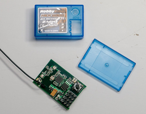
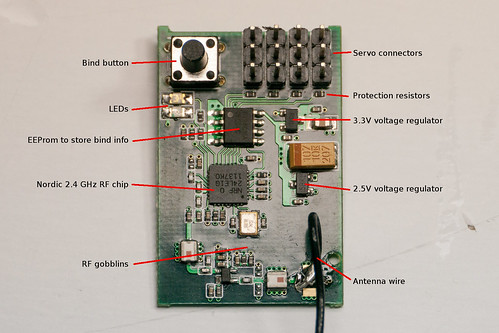
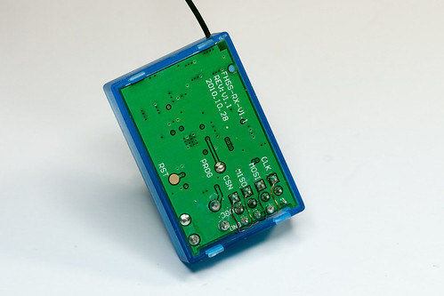
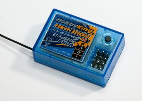
Starting point was an ordinary HKR3000 receiver that comes with the HK-310 car radio system. The receiver has quite a bit of unused volume inside the casing, ideal to add custom DIY electronics.
We will be using the signal pin on the battery connector to output our RS232-like signal from our light controller pre-processor to the actual light controller in the body. So the first job was to remove the protection resistor from the battery signal pin.
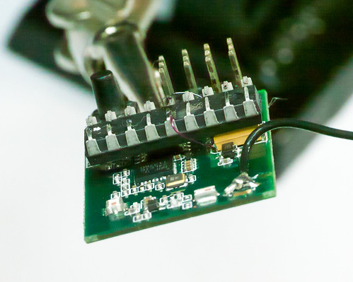
After removing the resistor that goes to the battery signal pin I added wires to the large capacitor on the 3.3V supply, which we will use to power our PIC micro-controller. I am using 0.19mm thick enamel wire.
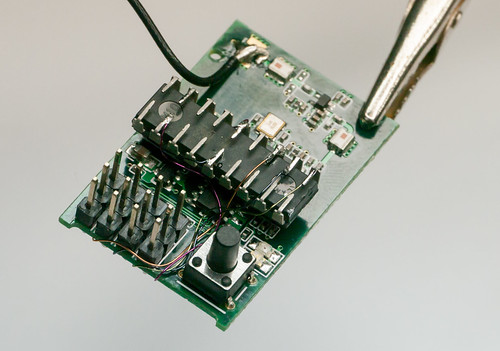
The pins on the PIC micro-controller have been bent down to fit inside the casing and the chip has been glued onto the capacitor, which is the tallest component on the PCB. I used CA glue. The supply wires were then soldered onto the micro-controller.
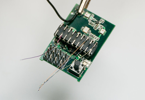
The four wires that go to the servo signal connector have been cut to length, pre-tinned and already soldered onto the PIC micro-controller. While for this application I could have used one of the tiny 8-pin PIC chips, I only had 16F628 available, so I used those.
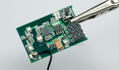
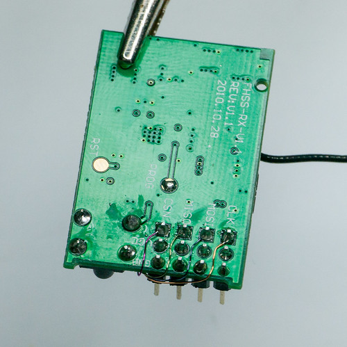
The servo signal wires soldered onto the signal pin of the connectors.
The wires were neatly put in the empty space between the connectors and the bind button.
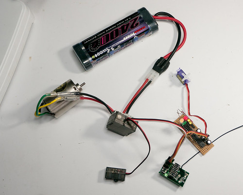
Testing time, using a cheap brushed China ESC and the slave light controller for the Tamiya XR311: it works!
The PCB has a notch at the connector side. This creates a gap in which the wires fit easily.
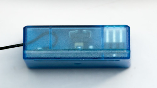
Closed up it looks just like any other HKR3000 receiver ...
... but if you look carefully you can see a bug inside :-)
Update 2013-01-30: Check out DIY RC Light controller pre-processor miniaturization on how to use a micro-controller in an SMD package for smaller receivers.
All articles in this series:
DIY car light controller for 3-channel RC
Pre-processor for the DIY RC Light controller
DIY RC Light controller pre-processor miniaturization
DIY RC Light Controller update
DIY RC Light Controller with WS2812B
Hi! Very interesting. I have a question. The 16F628 need to program?
ReplyDeleteYes, it needs to be programmed.
ReplyDeleteNote that this project is quite old. I have now built my own compatible receivers that already have such "Pre-Processor" function built in: https://github.com/laneboysrc/nrf24l01-rc
I also have separate Pre-Processors that work with any standard receiver: https://github.com/laneboysrc/rc-light-controller