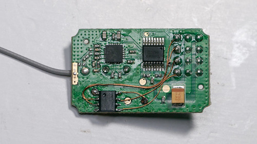
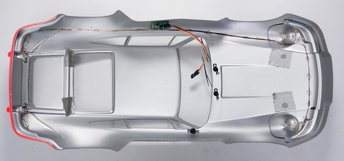
It has been a while since be blogged about our Light controller. In the meantime we have equipped more than ten cars with our custom electronics.
In this post we describe the changes we did along the way to the electronics and the firmware.
WARNING: This and other DIY projects are purely "at your own risk". If you are at all uncomfortable or inexperienced working with electronics, please reconsider doing the job yourself.
The light controller is designed to be controlled from a simple 3-channel RC car radio controller, such as the HobbyKing HK-310 or the FlySky GT3B. On those transmitters channel 3 is a simple on/off toggle switch.
To get realistic scale lighting, the light controller supports the following functions:
- Parking, Low-beam, Fog lamps and High-beam can be switched on/off manually using CH3
- Brake and Reverse lights are automatically controlled by monitoring the throttle channel. Since the original release the brake lights now automatically turn on for a short, random time when the throttle goes to neutral.
- Combined tail and brake light function in a single LED through controlling the brightness of the LED.
- Indicators only come on when you want to. You have to stay in neutral for 1 seconds, then hold the steering left/right for one second before they engage. This way normal driving does not trigger the indicators.
- Hazard lights can be switched on/off using CH3
- Programmable servo output designed to drive a steering wheel or a figures head
- Programmable servo output for a 2-speed gearbox
- Various customizable light patterns for a roof light bar
- Automatic centre and end-point adjustment for all channels
Compared to the original design, we upgraded the components used. The micro-controller is now a more modern Microchip PIC16F1825 in a small 14 pin package.
The LED driver is a TI TLC5940. This driver supports 16 constant-current outputs. The current on each output can be programmed in 64 steps, allowing for fine brightness adjustments without the need to run high-frequency PWM signals through your RC car.
16 outputs is enough for most light installations. If more lights are needed several light controllers can be cascaded -- though this function is not implemented in the software at this time.
In the original design with only 8 outputs, the LEDs had to be wired up in series. Since white and blue LEDs require voltages of 3V or more, the receiver voltage is not sufficient to drive two LEDs in series. We solved this in the original design by use of a DC-DC boost converter, generating around 8V. This DC-DC converter increased the cost of the controller significantly.
With the additional outputs available in the new design there is no need for the DC-DC converter anymore, each LED can be driven directly from a single output, so the 5V or 6V that your receiver runs with is sufficient.
With the light controller needing to have access to throttle, steering and CH3 of your receiver, wiring may become an issue -- especially because the light controller will be mounted on the body, while the receiver is on the chassis and the two need to be separated often.
We solved this by adding a tiny 8-pin micro-controller into our receivers. We call it a pre-processor, refer to our earlier blog post.
The pre-processor reads the three channels and outputs them as serial data using UART signalling. Usually the signal line of the battery connector on the receiver is unused, so we occupy it for connection to the light controller. Now only a single servo extension wire runs from the receiver to the body. Clean and easy to use.
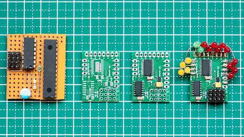
The light controller design is very simple, just two chips, a voltage regulator, two resistors and a few bypass capacitors. It can therefore easily be built on prototyping boards.
We also designed a PCB for SMD components. The board measures 30 x 23 mm, about the same size as a small 3-channel receiver.
The Eagle files for the schematics and layout as well as rendered Gerber files are available on Github. You can order the PCB directly from OSHPark for very little money. A word or warning though: the SMD version of the TLC5940 comes in a package with very small pin pitch of 0.65mm. It requires good soldering skills.
The firmware is also available in source code on Github. It is written in assembler using the open source gputils tools. You will find there the specific light implementation for all cars we have equipped so far, which should serve as a template for your own customizations.
In case you have any question don't hesitate to contact us!
All articles in this series:
DIY car light controller for 3-channel RC
Pre-processor for the DIY RC Light controller
DIY RC Light controller pre-processor miniaturization
DIY RC Light Controller update
DIY RC Light Controller with WS2812B


hey your link for the schematics and layout as well as rendered Gerber files is broken. please fix thanks keep up the good work
ReplyDeleteThanks for the heads-up, link is fixed now!
DeleteCan these be purchased?
ReplyDeleteThis is a hobby project and not commercially available. If you just need one or two pieces please contact me at laneboysrc@gmail.com and maybe we can work something out.
DeleteThe schismatics link is broken again :(
ReplyDeleteI am a complete noob at microchip programming so need all the help i can get from the schematics :)
Sorry for that, it is fixed now.
DeleteNote that there is a new version of the light controller using an ARM microcontroller which is easier to customize and richer in features.
Please start at https://github.com/laneboysrc/rc-light-controller, the description there should guide you to find which version is most suitable for you.
If you need help don't hesitate to contact me at laneboysrc@gmail.com!
cheers, Werner
Good day sir,im from malayisa doing 1/50 scale models,im looking smaller/miniture light control pcb similer to your design where i can get?
ReplyDeleteHi, please contact me at laneboysrc@gmail.com
Deletehttps://youtu.be/GODej1L2tQg
ReplyDelete