In recent years LEDs are appearing on the market that contain a controller chip. Currently the WS2812B is highly popular. It is a RGB LED that contains a simple chip inside. The LED is controlled through a single pin using a serial shift-register-like protocol. Multiple LEDs can be chained together; like a Christmas light.
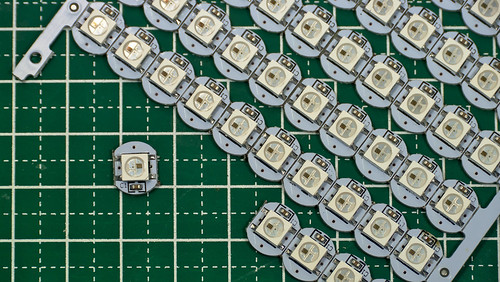
The WS2812B LED on a breakout-board for convenient mounting.
The WS2812B is an RGB LED with a built-in shift register like controller.
It has 4 pins: GND, Vdd, Data-in and Data-out. With only three wires going
from LED to LED, one can control each LEDs color and brigtness individually.
Using such LEDs makes wiring up a vehicle very easy: one only needs to run 3 wires from one LED to the next.
Also the control electronics becomes simpler as only a simple low pin-count device is needed.
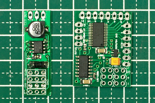
The WS2812/PL9823 DIY RC Car Light Controller on the left, compared to the earlier design based on the TI TLC5940.
Driving the WS2812/PL9823 LEDs requires only 4 cheap and easy to solder components!
The WS2812B is extremely cheap too. When ordered in 100 pcs quantity from China it is only slightly more expensive than a regular 5 mm white LED from the local hobby shop.
The WS2812B are SMD LEDs in a 5 x 5 mm square case. This makes mounting them in a traditional RC car light bucket, which is usually designed for 5 mm round dome style LEDs, inconvenient.
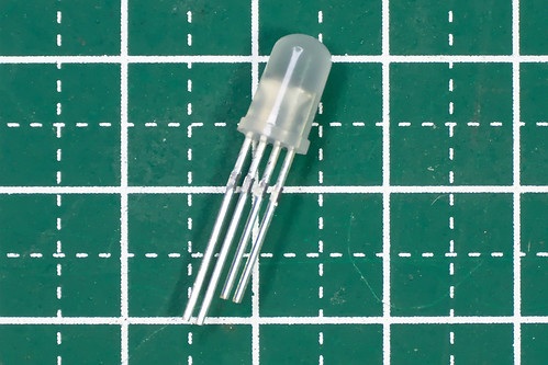
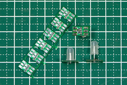
However, the PL9823 has the same functionality as the WS2812B and comes in a standard 5 mm dome encasing with four leads. The PL9823 is timing compatible with the WS2812B, so both LEDs can be mixed in the same string of lights.
The PL9823 has few downsides over the WS2812B:
- High power consumption of ~7-8mA even if the LED is off.
- When power is applied the LEDs usually light up blue until they receive valid data. The WS2812B stay off until data is received.
- Data format is red-green-blue , while WS2812B is green-red-blue. This can be easily dealt with in software though.
When using the WS2812 it is advisable to not buy the bare LED, but rather the ones that come on a tiny circuit board of ~10 x 10 mm. This board already contains the bypass capacitor and convenient terminals for soldering.
Unfortunately no such board seems to exist for the PL9823. It is possible to solder wires directly onto the leads of the LEDs, but due to the narrow pitch it is not fun. We have made a small break-out board, including bypass capacitor, ourself.
Compared to the light controller design using a TLC5940 chip, the narrow operating voltage range of the WS2812B or PL9823 based light controller is certainly a downside.. The WS2812B can operate between 3.5V to 5.3V, the PL9823 requires 4.5V to 6V. The PIC12F1840, a small 8-pin microcontroller, we are using can operate between 2.5V and 5.5V. This means that the light controller is best powered from a 5V BEC, or if the BEC operates at 6V a diode must be used to drop the voltage to the safe range.
The LEDs also do not tolerate any reverse voltage. When + and - are accidentally swapped they burn out immediately. Don't ask how we know...
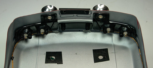
A great feature of the WS2812B or PL9823 based light controller is that the color of each LED can be programmed individually. In our Rally Legends Lancia Fulvia body shell the rear indicators and reversing lights are driven by a single LED, but by programming the LED to output either white or orange light we were still able to simulate reversing lights and indicators.
Unfortunately there does not seem to be any variant of the WS2812B or PL9823 that comes in a 3 mm dome factor, which is sometimes used in light buckets of Tamiya or HPI. Maybe with such a body the TLC5940 based light controller will be a better choice.
As with all our current DIY RC Light Controller iterations, firmware and hardware files are available for download on our Github page. Based on feedback from other users, we have also added pre-compiled HEX files for certain configurations as well as improved the documentation.
In case you have any question don't hesitate to contact us!
All articles in this series:
DIY car light controller for 3-channel RC
Pre-processor for the DIY RC Light controller
DIY RC Light controller pre-processor miniaturization
DIY RC Light Controller update
DIY RC Light Controller with WS2812B
Where can I order those PL9823 breakout boards?
ReplyDeletekind regards
Mark
Hi Mark,
ReplyDeleteThe files are at https://github.com/laneboysrc/rc-light-controller/tree/master/mk3-ws2812b-pic12f1840/electronics
They are in Eagle format. You can have them made in one of the numerous PCB manufactureres, check out https://pcbshopper.com/ to find one suitable for you. PCBs are really affordable nowadays.
If you only need a small number of boards then I can send you a few left-overs; contact me at laneboysrc@gmail.com