Light systems for RC cars are available for relatively little money. But for our Dingo I wanted something custom, something special. So I made my own.
The goal was to be able to control the lights from a simple 3-channel RC car radio controller, such as the HobbyKing HK-310 or the FlySky GT3B -- both of which we own.
The following functions have been implemented:
- Parking, Low-beam, Fog lamps and High-beam can be switched on/off using CH3
- Brake and Reverse lights are automatically controlled by monitoring the throttle channel
- Indicators only come on when you want to. You have to stay in neutral for 1 seconds, then hold the steering left/right for one second before they engage. This way normal driving does not trigger the indicators for more realism.
- Hazard lights can be switched on/off using CH3
- Programmable servo output designed to drive a steering wheel or a figures head
This video shows the functionality of the light controller:
WARNING: This and other DIY projects are purely "at your own risk". If you are at all uncomfortable or inexperienced working with electronics, please reconsider doing the job yourself.
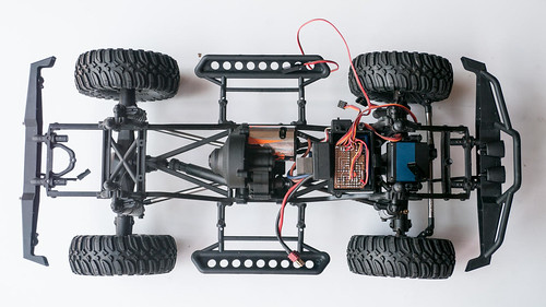
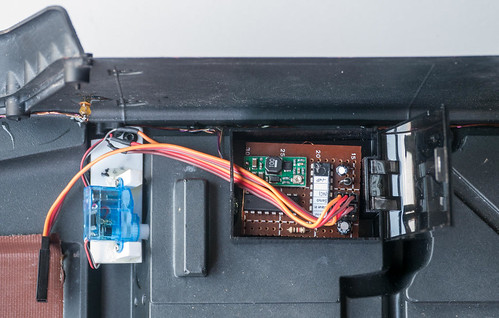
The system comprises of two circuit boards in a master-slave configuration. The master unit connects to the receiver. In our case it is housed together in with the receiver in the radio box of our Axial SCX10. A slave unit is mounted into the body. A single servo extension lead connects between them. This master-slave setup provides a simple and clean wiring solution, especially for cars like the SCX10 Dingo that has lights in the chassis as well as in the body.
The light controller configures throttle and steering automatically. It assumes that throttle and steering are in neutral when you switch the car on, and it adjusts its end points to the largest values it receives from the receiver when you move throttle and servo. No setup required!
Master and Slave units are based on the exact same hardware, but their firmware is different.
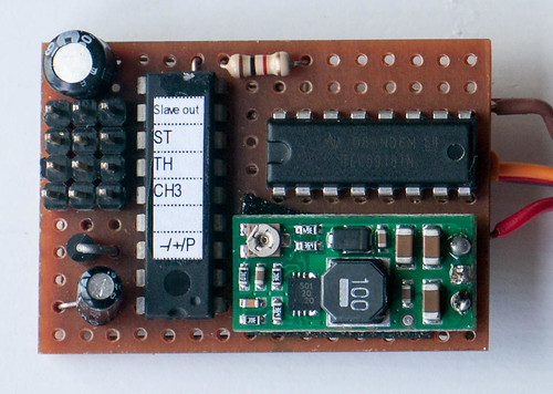
The master/slave unit comprises of the following components:
- PIC 16F628A microcontroller
- TI TLC5916 Constant Current LED driver
- Pololu Adjustable Boost Regulator
The LEDs are driven by a constant current of 19 mA. The LED voltage is up-converted to 7.5 V from the 5 or 6 Volt that the receiver is powered with so the LEDs stay equal brightness even if the NiMH batteries we use for trailing run low. 7.5 V is high enough for two high brightness LEDs yet low enough to not cause excessive waste of energy. If you are running a 2S LiPo you could run the LEDs directly from it and save space and cost for the boost regulator. Make sure you add a fuse though!
Both master and slave units can drive eight independent LED channels. A single LED channel can drive two high brightness LEDs or three normal LEDs in series. If more LED channels are needed, up to seven slave controllers could be daisy-chained. The slave controller can drive an LED channel either in half brightness or full brightness. We make use of this for the combined tail and brake light: a single LED is switched half brightness for tail light effect and full brightness for brake light.
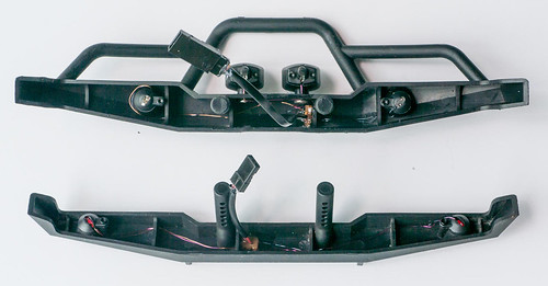
In total our Dingo has twenty LEDs on board. Six in the chassis (front and rear bumpers), and fourteen in the body. This required a lot of wiring. To use as little space as possible I used enamel wire. This is copper wire that is isolated with a special material that melts when you solder it. It is 0.19 mm thin and therefore very fiddly, but it means that even a bundle of eight wires together does not take up a lot of space.

The PIC 16F628A contains the control firmware. It reads the three channels from the receiver. Based on some business logic it sends information to the TLC5916 LED driver to turn LED channels on or off. The UART of the PIC is used to control slave light controller units.
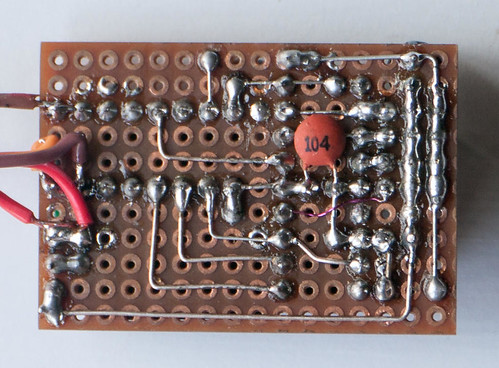
Due to limited resources available I built the light controllers from simple prototype boards using standard DIL and radial components. Yet the size turned out quite small: 42 x 29 x 12 mm -- about the same as a normal sized three channel receiver. If needed using a two layer PCB and SMD components the controller can easily be shrunk to half size.
Schematics and firmware are available on Github -- https://github.com/laneboysrc/rc-light-controller
Please use, reuse, or modify this design! And please share what you did!
All articles in this series:
DIY car light controller for 3-channel RC
Pre-processor for the DIY RC Light controller
DIY RC Light controller pre-processor miniaturization
DIY RC Light Controller update
DIY RC Light Controller with WS2812B
Hello,
ReplyDeletegreat job on custon light controller and thank you for a superior support on all my problems and questions.
My project with your light controller can be seen at Youtube:
http://www.youtube.com/watch?v=Pf3K9EzqM1I
http://www.youtube.com/watch?v=UgAUClb7cOI
Bye, Mladen
Hello,
ReplyDeletegreat job on building custom light controller and thank you for a superior support on all my problems and questions.
My work can be seen on Youtube:
-Subaru lights front
http://www.youtube.com/watch?v=Pf3K9EzqM1I
-Subaru lights rear
http://www.youtube.com/watch?v=UgAUClb7cOI
Bye, Mladen
Hi sir! Awesome DIY project. How i wish i have the skills like you do. That being said, have you considered making one for a fee? Thanks!
ReplyDeleteThanks for your kind words! Unfortunately time and skills do not allow to commercialize this project.
DeleteIf you are located in Singapore we can meet up and I certainly can help you equipping your car though.
hello
ReplyDeleteyou can add fuction simulator sound engine ? Or add beep beep to warring ?
A sound simulator will not work as the PIC I use does not have enough memory and processing power. But just a simple beep or horn sound should be possible.
DeleteI plan to do a engine sound system at some point in time ...
Hi I'm trying to create the hex file for the generic model from the source on github, but am struggling! I normally use mplab on windows. I have installed linux (debian) on a spare machine, and got gputils installed ok along with the source but can't figure what command is to create the hex file any help would be welcome. Thanks in advance
ReplyDeleteHi! You simply need to open a console window, "cd" into the directory where the firmware source code resides, and type "make". This will build all "cars", including generic. If you run "make generic" it will only build that one.
DeleteIf "make" is not installed, you need to "sudo apt-get install build-essentials" (at least on Ubuntu; Debian should be similar).
You can also build the code on Windows. GPUtils has a Windows port, and GNU Make too: http://gnuwin32.sourceforge.net/packages/make.htm
You will have to edit the makefile though regarding the rm command, which is not available on Windows.
Contact me on laneboysrc@gmail.com if I can help further!
Thanks so much for your help, now managed to compile it ok :-))
DeleteCan I order one of these.
ReplyDelete